General Indexer Information
This sections describes concepts that are applicable to most indexers irrespective of the brand of CNC or of the software used. The descriptions are also applicable no matter whether the indexer is mounted parallel to the X or Y axis.
There are two main sections of this General Information:
Concepts: How designs are translated into actual mechanical movements
Mechanics: Parts of the indexer and how to mount material for machining
Concepts
Terminology
Indexer: An indexer (or Rotary Indexing Head) is similar to a lathe in that it allows you to horizontally rotate a part being cut by the router or spindle. It differs from a lathe because it provides precise control of the rotation of the material whereas a lathe tends to rotate material continuously at a constant speed. With an indexer motion in X, Y, or Z can be coordinated with rotation of the material which allows for spirals, twists, wrapping of text, and even machining of 3D designs on a column.
Lathe: A lathe is a tool which spins a block of material while it is being cut to create an object which has symmetry about an axis of rotation. Typically a lathe is spinning the material at a constant rate independent of motion in the X, Y, or Z planes.
Fourth Axis: Three axis machining usually means motion in in the X, Y, and Z planes. A fourth axis frequently refers to adding rotation about the X or Y plane. This tutorial will refer to machining where X or Y movements are translated into rotational movement. This tutorial will not deal with designs where movement is happening simultaneously in all four axes. It will always be assumed that either the X or Y motion is replaced with rotational motion.
Rotary Machining: In this context is means translating movements in the X or Y place to be rotational movements so that a design is wrapped around a column.
Right Hand Rule
Some people find the following description of the right-hand rule helpful in understanding the relationship between XYZ and rotary movement.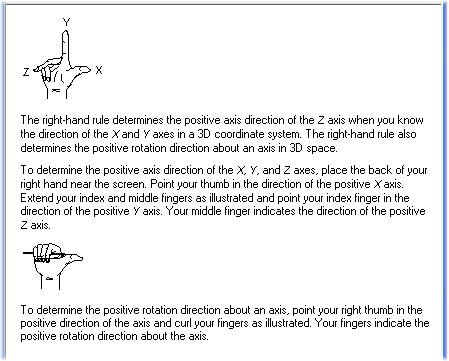
Basic Concept 1:
Rotary Machining takes a "flat" design and wraps it around a column
Rotary 101
The way that rotary support works is to translate moves from the X or Y axis and change them to a move on the rotary axis (usually referred to as the B axis) so the design is wrapped onto a cylinder. This is referred to as "Wrapped Rotary Axis Machining".
Perhaps this is easier to visualize if we take a common cylinder and show it laid out flat and then wrapped into a cylinder. For example:


The following shows how a dish style 3D design is wrapped around a cylinder.


Screen shots and images courtesy of Bill Schober
Basic Concept 2:
A spiral is achieved by using a design that is wider than the circumference of the cylinder
Rotary 102: Spirals
Spiral work is essentially wrapping a design around a column more than once. Referring to our visual aid, imagine a design that wraps around the cylinder three times:
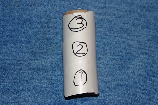
This is achieved by taking a long ribbon of material and wrapping it around the cylinder at an angle. For example:
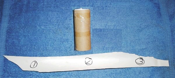
In this example the "ribbon" of material is three times wider than the circumference of the cylinder and one third as tall as the length cylinder.
In this video observe how the material spins multiple times to achieve the spiral design.
In the following example Bill Schober took the Serenity Prayer and wrapped it around a staff.


Mechanics
This section identifies common parts of an indexer and describes a method to prepare and load material into an indexer for machining.Parts of the Indexer
Headstock


The headstock is typically the part that has the motor connected to it. It also has a chuck with jaws that can be adjusted to the size of material. If the material is larger than the chuck then either the material can be cut down on the end, or a mounting plate can be attached to the material. The mounting plate will have a "knob" on it that will fit in the chuck.
Tailstock


The tailstock is a device used to support one end of the material mounted in an indexer. It applies support to the longitudinal rotary axis of a workpiece being machined. A lathe center is mounted in the tailstock and inserted against one end of the workpiece at the center. The tailstock does not move the material, rather it is stationary or turns passively while the workpiece rotates. Once material is mounted in the headstock the tailstock is moved close to the end of the material. It is locked in place then fine adjustments are done with a leadscrew to move it snugly into position. Do not over-tighten as it can split the material.


Indexer Mounting: X or Y?
For subsequent tutorials it will be important to know if your indexer is mounted parallel to the X axis or the Y axis.
Some examples of X mounted indexers:


Examples of Y mounted indexers:
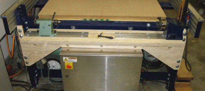

Photos coutesy of Jack Jarvis, James McGrew, Jim Van Vegten
Tutorials have all been generated for each mounting style. This information in this section applies to either style. In subsequent sections follow the examples that match your setup: parallel X or parallel Y.
Preparing Material and Mounting in the Indexer
Finding the Center of the Stock
In order to machine the material efficiently in the indexer the center needs to be located on each end to facilitate mounting in the headstock and tailstock. The most basic way to find the center of the material is to draw a line from one corner to the opposite corner (example: lower left to upper right) and repeat for the other direction (example: upper left to lower right). Where the two lines cross is the center of the material.
There are various center finders on the market which make it faster, easier, and more accurate to find the center of the material. Some are designed to be used with square or round material which can be handy as well.

Center Finder Tutorial on YouTube in a new window
The following photos (courtesy of Jim Van Vegten) show a headstock designed for handling small stock.


Handling Oversize Stock
If the material is too large to fit in the indexer chuck it either needs to be cut down or a piece needs to be attached to the material to adapt it to the indexer chuck. The photos below (courtesy of Jack Jarvis) shows indexing hubs which can be purchased through Legacy Woodworking.

Below is a design for a mounting jig that is used by Scott Cox:

Cutting Down Oversize Material
The information that follows demonstrates how to cut the stock down to size to fit into the indexer chuck. The basic steps are:- Mark the center point on each end of the material
- Draw a circle on the end that will go in the indexer chuck
- Saw around the diameter circle
- Use a chisel to remove the excess material
Compass Marking
Use a compass to mark the material to be removed. The compass should be set to a diameter that will fit the indexer chuck. Set the point of the compass on the center point that was marked in the previous step and then draw a circle.Compass Tutorial on YouTube in a new window
Saw Around the Center
Set the depth of cut on the saw so it stays on the outside of the circle that was drawn with the compass. Cut on all four sides.Saw Tutorial on YouTube in a new window
Chisel Off the Excess Material
Use a chisel to remove the material that was undercut with the saw.Chisel Tutorial on YouTube in a new window
Mounting Material in the Indexer
Mounting Material in the Indexer on YouTube in a new window
Zeroing the Bit
I strongly recommend using the center of the material as the Z-zero point.
The easiest way to do this is to zero off of some known point on the tailstock and adjust your Z height accordingly. On my particular setup the top of the tailstock is exacly 0.750" above the center of the cylinder. When I set Z-zero for rotary work I use the following steps:
- Run my Z-zero routine to zero off the top center of the tailstock
- Jog XY to move the bit off to the side of the indexer
- Move the Z down 0.75
- Reset the Z to zero
- Move the Z up to a safe height so it will clear the material
- Move to XY home
Thin Stock Support
by Jack Jarvis
When carving things like balusters, spirals, and other long thin (and some not so thin) parts you need to compensate for the downward and lateral flex exerted on your material from both the tool pushing downward and spinning along with the weakening of the structure when doing something like hollow spirals. The results of these pressures are tragically illustrated here.
In order to relieve these pressures I tried to figure out what could i use to keep my work from being ruined. After some experimentation with various designs I spotted a pair of old toy rollerskates from my granddaughter that she outgrew. Because they had an adjustment that allowed the rollers to be moved closer together this was perfect for what I was trying to do.
As in the above pictures you may notice that the actual profile cut into the material for the spirals was not very deep and the jig as you see it in will work well.
However if you are doing a design such as in
what you will find that you are cutting away alot of material and in doing so you now have no support underneath. To solve that problem I revised the jig so that I had springs inserted under the skate to exert upward pressure to support the stock as material is taken away.
Other designs I've worked on is a design that ran parallel to the X axis with that looked like two rolling pins. You could also use a couple pieces of PVC pipe.
Another componnent of thin stock support is lateral pressure. The problem when you start cutting into material is that it loses its lateral strength especially when making a hollow spiral.

Making a Hollow Spiral
by Jack JarvisTo create a hollow spiral is fairly simple in principle.
- Take a board equal to twice the length of the material you want to end up with.
- Take a core box bit running a half circle down the middle
- Cut it in half
- Join the two halves which form your round empty center after glue up


After joining the two halves you need to have internal support when cutting through the material to get to the center.


You need to have a dowel in the center that fits snuggly to support the underside of the spirals when cut.
You are now prepared to make your spiral. Use the appropriate bit with the toolpath or program you use to create your toolpath. This is a 3" rope molding bit. See Magnate.net Rope moulding bits:

->Rope Bits at Magnate.Net
After you make your spiral toolpath you leave all your settings alone and change your bit to a .25 straight flute bit. The spiral up and downshear bits have a tendancy to grab the sides of the spirals and vibrate the material and can break it.
Take a copy of the original toolpath used to make the 3" spiral and change the cutting depth to .10 or .15 per pass. Z-zero the bit at the material surface (or a bit above).
After the first pass lower the bit to the depth you just cut (or a hair above) and reZero the Z. Run the toolpath again. Repeat this process while cutting about .10 per pass till you cut through and expose the center dowel.
When you expose the center you will end up with a piece that looks like these.


