Examples for Indexers Mounted Parallel to the Y Axis
These examples are written for use with an rotary axis that is parallel to the Y axis. This means that X values will be translated into rotational movements that are wrapped around the column.
Examples of Y mounted indexers: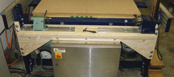
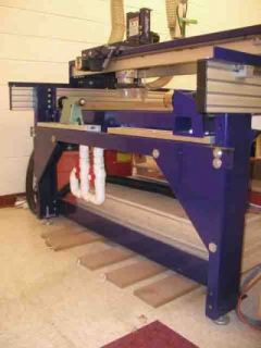
Translating from Flat to Rotary
If you are wrapping the X values around the rotary axis:
The leftmost point on the design would be at 0º
Midway between the left and right borders would be 180º
The rightmost point on the design would be at 360º
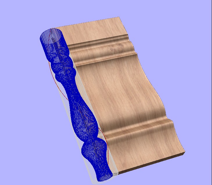
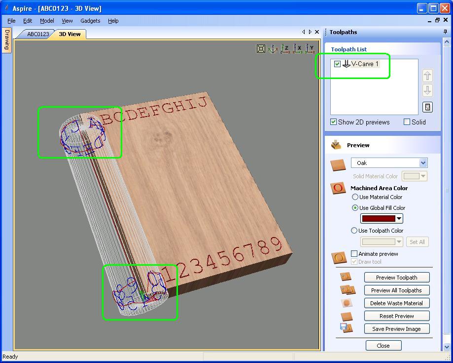
Now look at the preview of the flat design and the toolpath wrapped around the cylinder. This can help us visualize what the final result will look like even though we don't have the typical preview we are used to from Vectric products.
Right Hand Rule
Some people find the following description of the right-hand rule helpful in understanding the relationship between XYZ and rotary movement.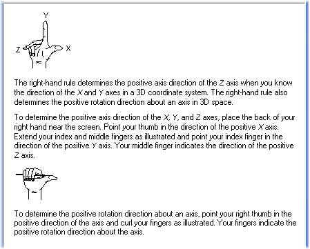
How Does the Code Change for Rotary Work?
Let's look at how the code changes when we compare a conventional toolpath to a rotary toolpath. For this example the toolpath will move from A to B to C to D and back to A. The origin is specified as the lower left corner. The workpiece is 10" wide by 16" tall.G Code Example
| G Code | ||
| Point | Flat | Rotary |
| A (0,0) | N190X0.0000Y0.0000F100.2 | N230 G1 A0.0000 Y0.0000 Z1.6500 F30.0 |
| B (5,8) | N210G1X5.0000Y8.0000F100.2 | N240 G1 A-180.0000 Y8.0000 Z1.6500 F100.2 |
| C (10,16) | N220G1X10.0000Y16.0000 | N250 G1 A-360.0000 Y16.0000 Z1.6500 |
| D (0,16) | N230G1Y0.0000 | N260 G1 A-360.0000 Y0.0000 Z1.6500 |
| A (0,0) | N240G1X0.0000 | N270 G1 A0.0000 Y0.0000 Z1.6500 |
| Shopbot Code | ||
| Point | Flat | Rotary |
| A (0,0) | M3,0.000000,0.000000,1.650000 | M5,,0.0000,1.6500,,0.0000 |
| B (5,8) | M3,5.00,8.000000,1.650000 | M5,,8.0000,1.6500,,180.00 |
| C (10,16) | M3,10.00,16.000000,1.650000 | M5,,16.0000,1.6500,,360.00 |
| D (0,16) | M3,10.00,0.000000,1.650000 | M5,,0.0000,1.6500,,360.00 |
| A (0,0) | M3,0.000000,0.000000,1.650000 | M5,,0.0000,1.6500,,0.0000 |
Note how, for rotary toolpaths, the X values have been translated to angles.
| X 0 became 0º |
| X 5 became 180º |
| X 10 became 360º |
The software does the math to convert inches (or millimeters) to degrees. It isn't terribly complicated. Basically, take the circumference of the cylinder and divide it into 360 pieces.
Imagine a bit just grazing the surface of the cylinder and then the cylinder rotates. How long would the line be that the bit makes on the cylinder? Here's a table that shows how long the line would be if the cylinder rotates 1º:
| Diameter | Circumferrence | 1º |
| 1 | 3.14 | 0.0087 |
| 2 | 6.28 | 0.0175 |
| 3 | 9.42 | 0.0262 |
| 3.5 | 11.00 | 0.0305 |
| 4 | 12.57 | 0.0349 |
| 6 | 18.85 | 0.0524 |
| 8 | 25.13 | 0.0698 |
| 10 | 31.42 | 0.0873 |
| 12 | 37.70 | 0.1047 |
Rotary 102: Spirals
Spiral work is essentially wrapping a design around a column more than once. Referring to our visual aid, imagine a design that wraps around the cylinder three times: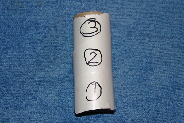
This is achieved by taking a long, this ribbon of material and wrapping it around the cylinder at an angle. For example:
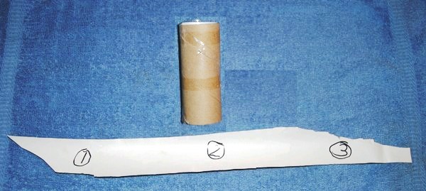
In this example the "ribbon" of material is three times wider than the circumference of the cylinder and one third as tall as the length cylinder.
Creating a Wrapped Job
Now that we have some of the basics let's look at creating a simple job using rotary output. The easiest way to do this is to use the Wrapped Job Setup gadget under the Gadgets menu and the Wrapping submenu. The advantage of using the Wrapped Job Setup gadget is that it performs some of the math for you. This is especially important when your design wraps around the cylinder multiple times. See below.
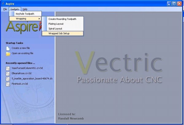
Depending on how Windows is configured you may be able to use the following keystroke sequence: <alt><G><W><W> Important: You cannot have a project opened when you use the Wrapped Job Setup gadget.
Wrapped Job Setup Dialog
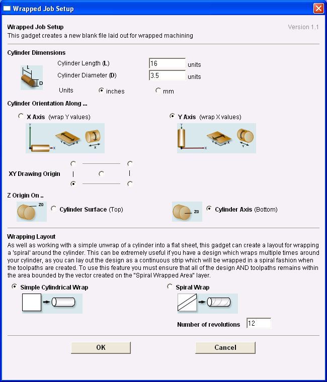
Let's walk through the fields:
Cylinder Length (L):
This seems pretty self-explanatory -- how long is the piece? Be careful that you don't set it longer than your material. If you have an indexer setup like mine then it is possible to crash the router bit into the headstock or the tailstock. You may wish to choose a length shorter than your actual material if you wish to leave one or both ends square, such as on a baluster.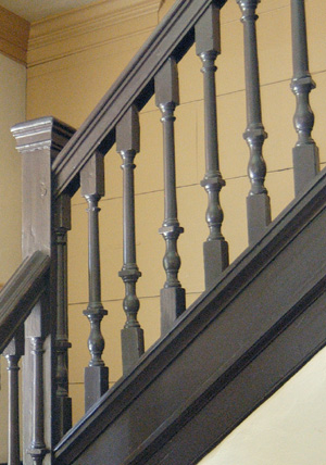
Cylinder Diameter (D):
The software uses this value to calculate circumference of the cylinder using the formula:
C = p x D
or in other words....
Cylinder Circumference = 3.14 x Diameter of the cylinder
If you are starting with good quality material you would just enter the diameter of the material. This is the diameter of the piece after its rounded and smoothed.
Suppose I have a 5 inch diameter fencepost with a very uneven surface -- perhaps just a log with the bark removed. Because of surface defects I may want to machine it down to 4.5" in diameter before it is usable. So for the purposes of this job setup I would say that my material is 4.5" diameter.
Cylinder Orientation Along...:
Typically the long axis of a CNC is the X axis and the shorter one is the Y axis. Choose the one that matches your indexer setup.
XY Drawing Origin:
This identifies where "home" is. Think of this in the same way you would for conventional machining of flat sheet material. My recommendation is to start with the origin where you are used to it. If you are used to having the origin in the lower left corner the choose that. If you are used to home in the center of the workpiece then use that.
The following table translates the origin settings to a rotary definition:
| Origin | Position | Rotary |
| Lower Left | Head Stock | 0: |
| Lower Right | Head Stock | 360: |
| Center | Midway | 180: |
| Upper Left | Tail Stock | 0: |
| Upper Right | Tail Stock | 360: |
Recall that 0: and 360: are the same point on the cylinder. Therefore choosing a Lower Left or Lower Right origin will look like the same point. Likewise an origin of Upper Left or Upper Right will look like the same home position.
Again, start out using an origin that you are used to.
Z Origin:

I strongly recommend defining the Z origin as the cylinder axis.
One of the more powerful features of indexer work is achieved by using bit changes and a few specialized bits. It will be difficult to re-zero bits to the material surface if it has been machined away.
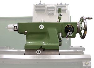
Wrapping Layout:
While you are learning rotary machining it is best to start with the Simple Cylindrical Wrap.
With a Simple Cylindrical Wrap the work area is the length of the cylinder and the width is the circumference of the cylinder (3.14 x diameter).
For example, suppose you had a 16 inch long 4x4. In the U.S. a 4x4 is really 3.5" x 3.5" or 89mm x 89mm. When filling out the Wrapped Job Setup dialog the Length would be 16 and the Diameter would be 3.5. The software calculates the circumference of the cylinder as 3.5 x 3.14159=10.9956. With a simple cylindrical wrap the work area would be 16" tall by 10.9956" wide.
Video: Wrapped Job Setup
Video on the Web
Downloadable Video in a Zip file
Exercise 1: Simple Layout
Use the Wrapped Job Setup with the following values:
Click OK
A new blank job is opened. Now look at the size of the work area using Edit/Job Size and Position.
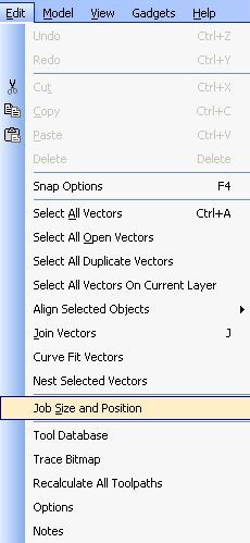
You should see the following results:
The width of job is 10.9956" which is the circumference of the cylinder
The height of the job is 16" which is the length of the cylinder
The thickness of 1.75" is one half of the cylinder diameter
Exercise 2: ABCs and 123s
Now that we have created an empty project for rotary work let's create a very simple design and see how it works both as a flat design and as rotary output. We aren't going to carve anything at this point. This is just to help us understand how the rotary translation works.
Using the layout from Exercise 1 (a 16" long cylinder with a 3.5" diameter) create a band of 1" tall text on the top and bottom for the design.
- Choose the Draw Text tool
- Set the text size to 1"
- Select the Courier New typeface
- Enter the text: 0123456789
- Center the text and position it at the bottom of the design
- Create a new group of 1" text: ABCDEFGHIJ
- Center the text and position it at the top of the design
Choose a V-carve toolpath a 90: V-bit. The results should look similat to this:
This is the type of preview we've come to know and love with Vectric products.
Next, enable drawing of the material block by selecting View/Draw Material Block:
Now let's enable rotary. Choose View/Toolpath Drawing/Wrap X Values (around Y axis)
A wireframe representation of the cylinder displays:
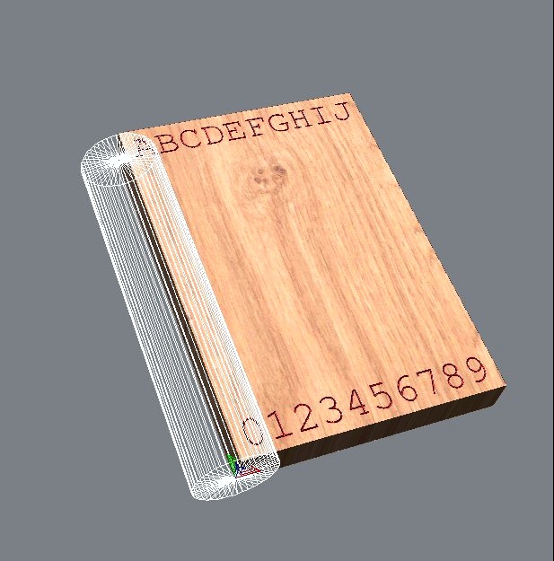
Click the checkbox for the V-carve toolpath. Notice that the toolpath displays on the cylinder. Observe how the text and numbers are wrapping around the column.
Video: View/Toolpath Drawing/Wrap X values
Video on the Web
Downloadable Video in a Zip file
Exercise 3: Square Peg, Round Hole
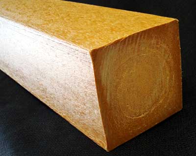
Frequently round material is not readily available for machining. Most often you will start with square material that needs to be rounded. The Vectric software has a gadget that optimizes a toolpath for rounding a square blank. It will round off one corner and then rotate the piece to opposite side to round off that corner. This is done to try and minimize stresses as the piece is rounded. Then the final two corners are rounded off.
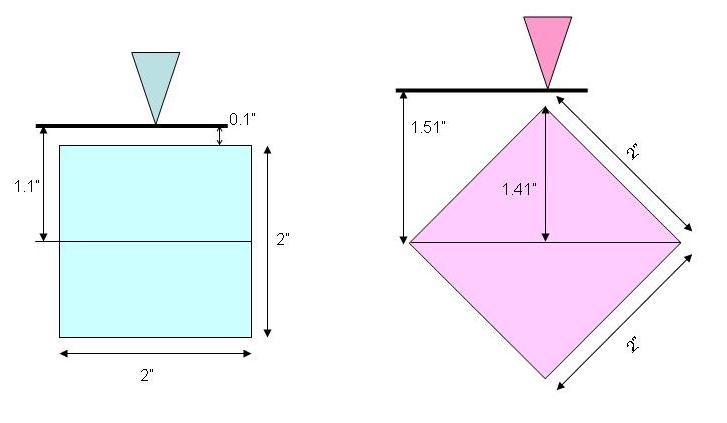
One thing you need to be aware of is that you will need extra Z height when rounding a square blank because the bit needs to remain above the material as the blank is rotated from one corner to the next. Perhaps this picture explains it best:
Here is a brief video that shows how the material is rotated for rounding. Note that extra Z clearance is needed above the squared corner.
You must use the Wrapped Job Setup gadget before you can use the Create Rounding Toolpath gadget.
Invoke the gadget using Gadgets/Wrapping/Create Rounding Toolpath:
The dialog box comes up:
The values at the bottom of the dialog (length, diameter, Cylinder Orientation) should flow through from the Job Setup gadget.
Click the radio button to select the square blank. You may need to enter the value for the square stock if it is not filled in correctly.
Under Machining Method click the radio button for Optimized Raster:
For Tool I usually select a 1" ballnose bit with a 10% stepover. This gives me a good finished surface.
Click OK to dismiss the dialog box.
Press
If you preview the toolpath without enabling Rotary view you would see something like:
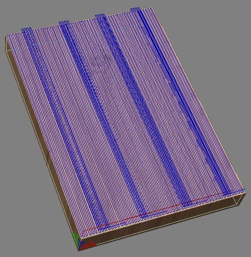
but if you enable rotary view like we did in Exercise 2 you would see:
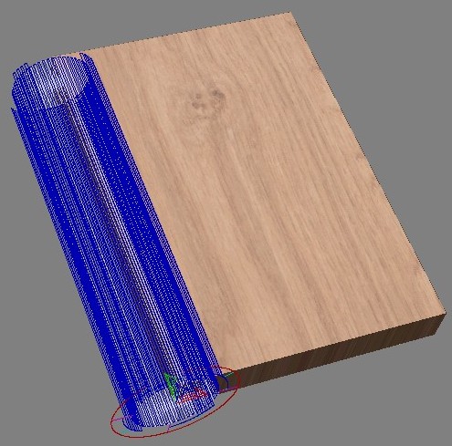
and if you look at it from the Y end you may get a better picture of how the square blank will be rounded. Basically the corners are removed and then the entire surface is smoothed:
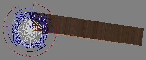
Try unchecking and checking View/Color Shaded View to see when that works better for you.
Now its time to create some chips. Try taking a 16" 4x4 and rounding it. We will use the rounded blank in the next exercise.
Rounding Videos
Videos courtesy of Stan KernExercise 4: A Simple Fluted Column
Video: FlutingVideo on the Web
Downloadable Video in a Zip file
Flutes and Reeds are decorative embellishments used in architcture, cabinetry, and furniture.
One definition of fluting is a semi-cylindrical vertical groove in a column. In CNC work fluting is usually done with a ballnose bit.
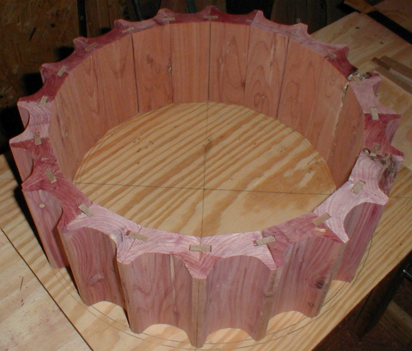

Flutes being cut courtesy of Stan Kern:
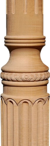
Reeding is the reverse of fluting. Reeding is an edge with a profile consisting of a series of parallel convex moldings, each of which called a reed. In CNC work reeding is typically done with a roundover bit. Sources for these bits are Woodline.com and Magnate.net. See below for examples of reeding:
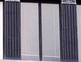
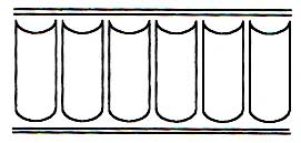

Some examples of a combintaion of fluting and reeding:
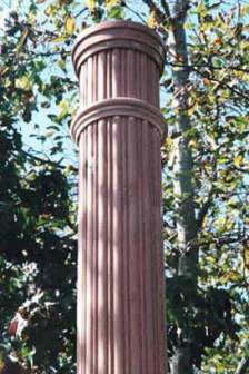
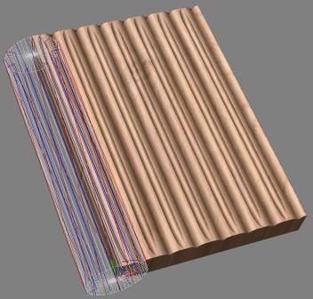
In this exercise we will make a simple fluted column using the Fluting Layout gadget.
The gadget uniformly spaces lines across the work area. You tell it the number of lines you want and it determines how far apart to space them so they are evenly distributed. The power of this comes from choices of toolpath style (profile-on-vector or fluting) and the bit used (straight, ballnose, V-bit, roundover, Ogee, etc.). Examples will be shown later.
Create a fluting toolpath on a 16" long, 3.5" diameter column using the following settings:
The gadget made two sets of vectors and has automatically grouped them and placed them on different layers. The vertical lines are on a layer called Fluting Vectors and the horizontal lines are on a later called Cove Vectors.
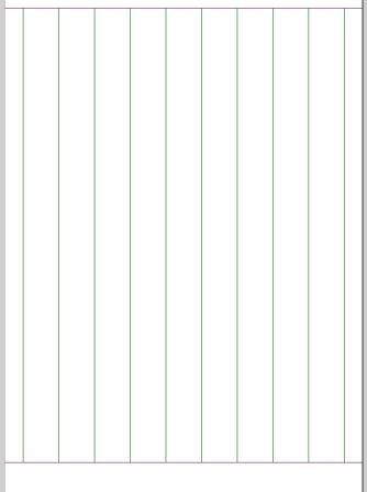
For now we are going to ignore the Cove Vectors and just preview the Fluting Vecotrs using different toolpaths and bits. It is strongly recommended that you preview each of these on your own system. Pay attention to estimated machine times as well. It is possible to get impressive results with a short toolpath.
Profile Toolpaths
Profile: 1" Ballnose @0.5" deep
Use a Profile Toolpath, machine On vector, with a 1" ballnose at 0.5" depth: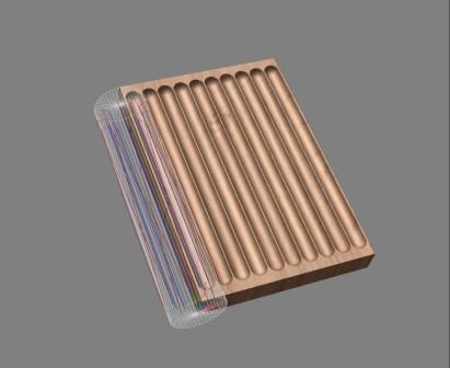
Profile: 1/4" End Mill @ 0.25" deep
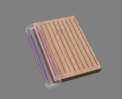
Profile: 1.25" 90: V-Bit @ 0.5" deep
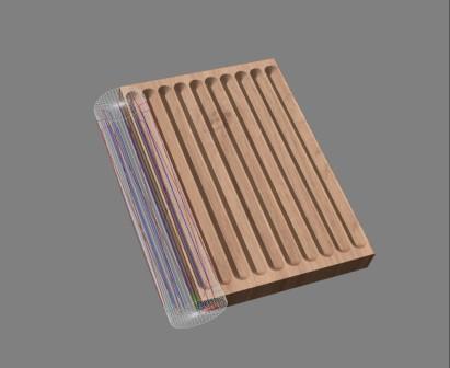
Profile: 1" roundover with 0.5" radius @ 0.5" deep
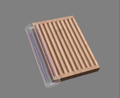
Profile: Ogee - 1/4" Rads 1 1/4" @ 0.325" deep
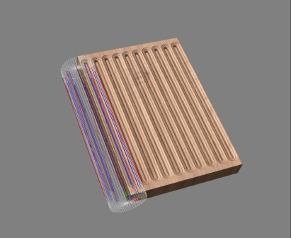
Fluting Toolpaths
Fluting: 1" Ballnose @0.5" deep
Use a Fluting Toolpath, with a 1" ballnose at 0.5" depth, Ramp at start and end, Ramp 100%, with a smooth ramp type: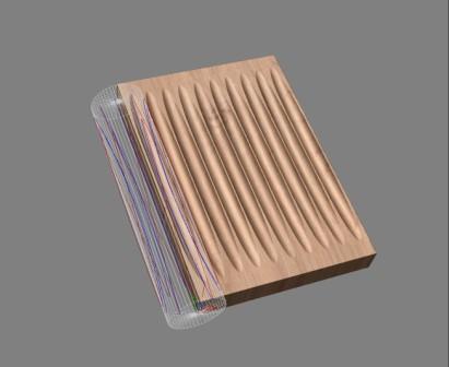
Vary the cut depth from 0.5 to 0.1. Recalculate the toolpath and refresh the preview. How does that change the appearance?
Change to Ramp Over Complete Length and observe the effect.
Change to Ramp at Start and End with a 2" ramp length and preview the results.
Change the ramp type from smooth to linear. You may be able to see a hard transition.
Fluting: 1.25" 90: V-Bit @0.25" deep
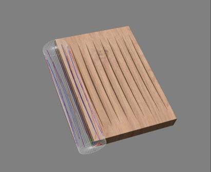
Try changing different fluting parameters with the V-bit and observe the effect.
Fluting: 0.5" End Mill with 2" ramp lengths @0.5" deep
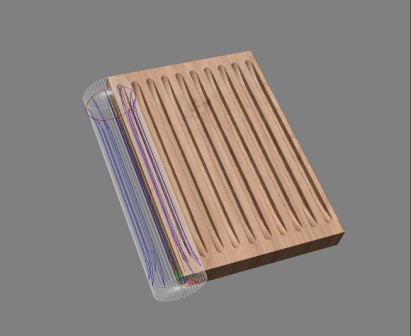
Observe the impact as you vary different fluting parameters with the end mill.
When you come across a design that you like, try carving that design on the rounded cylinder that you made in Exercise 3.
Exercise 4a: Making a Tapered Column in V-Carve Pro
Video: Tapered Column in V-Carve ProVideo on the Web
Downloadable Video in a Zip file
Here is a trick for making a tapered column in V-Carve Pro.
- Use the Fluting Layout Gadget and give it a large number of lines (For a 3.5" diameter column and a 1" ballnose use 110 lines)
- Use the Fluting toolpath
- For Flute Type choose Ramp Over Complete Length
- For Ramp Type choose Linear for a straight taper or Smooth for a curved taper
- For Flute Depth enter half the amount that you want the diameter to change by (remember that it is getting machined on "both" sides of the column) Example: if the column is 3.5" in diameter and you want it to taper down to 2.5" in diameter then (3.5-2.5)/2 = 0.5
Now, where the I come up with 110 for the number of lines? When doing 3D work, a stepover of 10% (or smaller) works well. If I'm using a 1" ballnose bit then a 10% stepover would be 0.1". If I divide the width of the material by the stepover I get the number of lines.
(Material Width)/(Bit Stepover)=Lines
(10.9956/0.1)=110
If I only had a 0.125" ballnose then...
(10.9956/0.0125)=880 lines
so it would take a lot longer to machine the tapered column.
Replicating an Existing Rotary Design in Aspire
A customer approaches you with a problem: their new puppy has decided to use the leg of an antique writing desk as a chew toy. You have been asked to make a replacement of the original. Regardless of all the issues with matching stain color and wood grain and finish you decide to take on the project. Here are the steps that I might follow:- Measure the item (length, width at a few key places)
- Photograph the item
- Wrapped Job Setup in Aspire
- Import image
- Trace Bitmap
- Scale Vectors
- Node Edit the vectors (optional)
- Split the design lengthwise and delete the left half
- Make a 2 rail sweep using the right half of the shape
- Toolpath
- Machine the part
Measure the Item
Measure the object at a few key points for reference. For our example table leg the length of the rotary part is 18" long. The original was turned from a blank that was 2.75" in diameter.Photograph the item
Take a picture of the item to be replicated. Make sure to photograph it as straight-on as possible. Try and get far back and zoom in since some camera wide angle lenses can cause the image to bow outward in the middle. Try for a good background so it is easy to discern the shape of the object. I've included a sample image that we will use for this exercise. Download it to your computer in order to follow along.Wrapped Job Setup
In Aspire create a new wrapped job using Gadgets/Wrapping/Wrapped Job Setup. In this example specify the length as 18" and the diameter as 2.75".Import the image into Aspire
Choose File/Import/Bitmap and bring the photograph. Zoom in or out as needed.Trace Bitmap
The way to trace the bitmap is somewhat subjective. Some prefer to switch the selector to Black/White while others prefer to work in color. All that matters is that you get a reasonably good trace of the image. You have the option of touching up the trace with node editing so you don't need to be too obsessive at this point.Select and Scale the Vectors
Select the vectors from the bitmap trace and scale them. In this example I recommend scaling the height 18". After scaling note that the width is reasonably close to 2.75".Node Editing
Now that we have vectors compare the design in Aspire to the actual measurements that you took of the original part. Use node editing to adjust the shape as needed to match the original. You may not need to be overly obsessive about this. If the original was not made using CNC then you will find that all the parts are not identical. Table legs made by hand on a lathe, for example, are unlikely to be identical.Split the design in half lengthwise and delete the left half
There are many ways to accomplish the next step. I'll document one technique that I use.- Ensure the design is centered in the work area
- Draw a rectangle that is the height of the work area and half the width.
- Select vectors for the design and for the rectangle
- Click on the "Keep Overlap Vectors" icon
- You are left with the right hand portion of the design with a line down what had been the center
- Use node editing to get rid of the lefthand line (delete span)
Make a 2 rail sweep using the right half of the shape
The next step is to create a 2 rail sweep using the profile for the shape. I prefer to move the shape we have been working with off to the left of the work space. Now we need rails at the top and bottom of the work area. I do this by drawing a rectangle the same size as the work area and then deleting the left and right spans. Make sure the starting point for both the top and bottom spans is on the left.
Select the top rail, the bottom rail, and the shape vector that we moved off to the left. Click on the 2 Rail Sweep icon.
Click Add.
Click Make Component
Close the 2 rail sweep dialog.Toolpath
Let's toolpath and preview the design. Since we are machining the entire work area we don't have to create a boundry area, but I usually do by creating a rectangle that is the same size as the work area. Select that rectangle and then navigate to the Toolpaths view (the shortcut key is F12).
Click on the icon for Create Finishing Toolpath.
Specify a 0.25" ballnose bit with a raster profile set to 90º.
Turn on the material block (View/Draw Material Block)
Turn on the Rotary View (View/Toolpath Drawing/Wrap X Values
Preview the toolpaths
Make sure the check box by the toolpath is selected
Play around with this by selecting different size ballnose bits and looking at the estimated machining time.Machine the part
When you have a design and machine time that you like try cutting the part. Downloadable Table Leg Example Zip file
Other Useful Resources
There is a lot of good information at Legacy Woodworking. Reading and watching videos on this web site is a good way to start thinking "rotary".